Fan Control Switch Wiring Diagram
This wiring diagram illustrates the connections for a ceiling fan and light with two switches a speed controller for the fan and a dimmer for the lights. Wiring for 3 speed fan switch what color wires correspond to the l, 1, 2, 3 designations on the back of the switch.
wiring diagram electrical inspirational auto wiring

The black wire on the fan is connected to the other switch load wire.

Fan control switch wiring diagram. This wiring diagram illustrates the connections for a ceiling fan and light with two switches, a speed controller for the fan and a dimmer for the lights. Wiring wiring must be in accordance with as/nzs3000:2007 and local supply regulations. Using the (see diagram #3 on reverse side).page 1.
It shows the components of the circuit as simplified shapes and the knack and signal connections in the middle of the devices. Replacing with hunter model 27182 dimmer & fan control switch. As you can see, we switched the hot line going to the light kit by inserting the switch.
Essentially the wire leading from the pcm db pk which supplies. Plug in the wire harness into the fan control module. Wiring diagram for carrier fan coil readingrat pertaining to fan coil unit schematic diagram image size 639 x 600 px and to view image details please click the image.
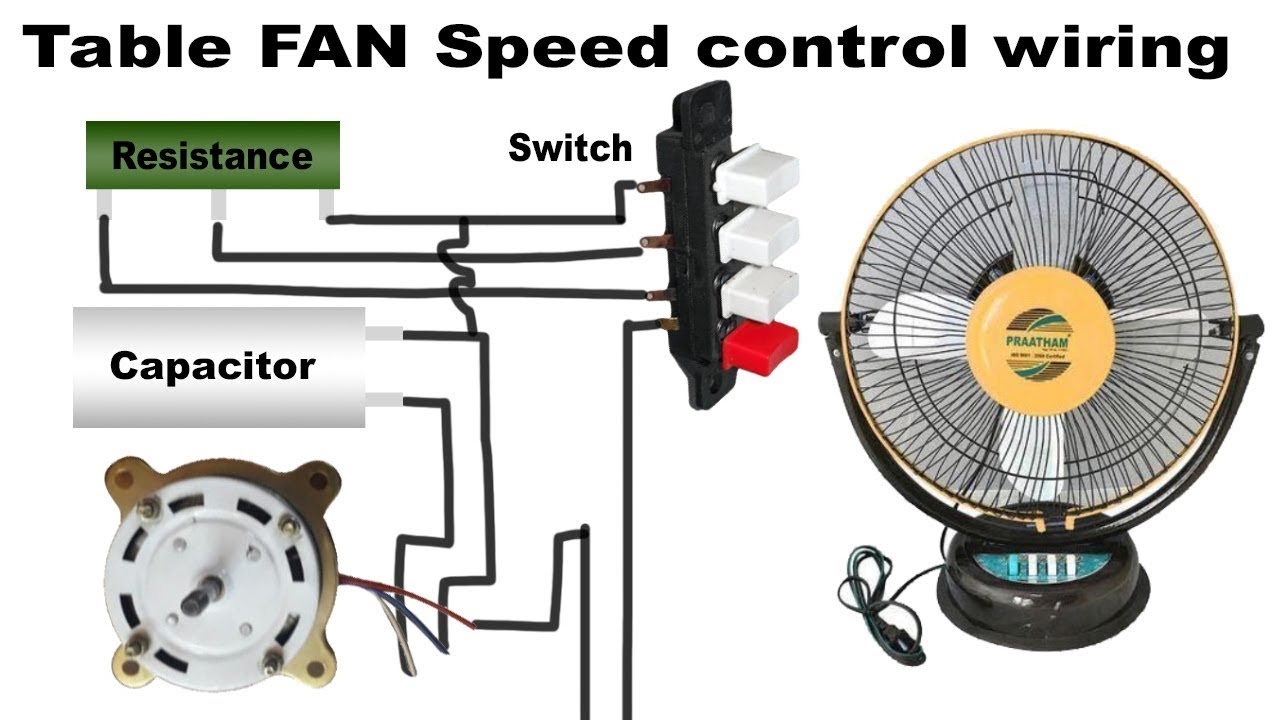
Connect the black wire from the ceiling to the black wire from the receiver. So in the above diagram the fan speed regulating switch contacts on l, 3 and 1 side and the line current is start to run wire of fan and 1.5 uf and the fan on low speed. Ceiling fan replacement speed control switch for 3 speed 4 wire zing ear
One way the fan should run while flipped the other way fan should not run until radiator temperature is high enough to turn on fan. Make sure that all of the wires are first pulled through the electrical box to ensure that the face place will fit securely against the wall. Many people use simple 12/2 (romex) with a ground wire to make this loop.
This one, although it came in a westinghouse package marked , is also a zing ear with the same number. Here the input of each controller is spliced to the black source wire with a. Ground connection diagram is shown.
Suggested by brian l, this will only work with the non remote based fans, if it has a remote it likely wont work, i don't much care for remote. Suggested electric fan wiring diagrams converting a 12 volt switch into a ground switch these diagrams show the use of relays, on/off sensors, on/off switches and on/off fan controllers. ( with ground) both white wires are connected together, leaving the black wires to be hooked up to the new switch.
In this diagram, the black wire of the ceiling fan is for the fan, and the blue wire is for the light kit. Wiring diagrams are provided with all fans. From my understanding this unit is just a temprature controlled relay , , adjustable, car, control, diagram, electric, fan, firebird, imperial, instructions.
As honeywell's illustration shows, the two fan terminals are on the upper and lower left side of the control. Wiring diagrams are shown on pages n. It shows how the electrical wires are interconnected and can also show where fixtures and components might be coupled to the system.
Use this arrangement when the source is at the switches. Radiator fan switch wiring diagram. Lets see the fan on med speed.
Connect the three white wires from the ceiling, fan, and receiver together. A wiring diagram is a straightforward visual representation from the physical connections and physical layout of your electrical system or circuit. The wiring for this type of electrical connection looks like this:
The wiring diagram above depicts the blue wire from the fan connected to the load wire from one switch. This capacitance based fan speed controller gives 3 speed control of ceiling requires only two wires at the switch point, as per the wiring diagram below. No need to use the pull chains unless you want to change the fan speed.
The light and fan are controlled independently of each other using the wall switches. Also read ceiling fan capacitor connection diagram 3 wire ceiling fan capacitor diagram 5 wire ceiling fan capacitor diagram and installation 4 wires come out of wall.
Wire up the fan speed switch control switch by following the normal wiring standards. All fans must be earthed in accordance with as/nzs3000:2007 and local supply regulations. The new switch has a black, red & blue wire ( green for ground).
As a result, many homeowners must use a single switch to control the light and/or both aspects of their ceiling fans. Thermostat wireless control unit specifications srw series wireless fan coil control unit is constituted with a thermostat remote and a receiver combined with valve actuator or not.
Ceiling Fan Speed Control Wiring Diagram Collection

Ceiling Fan Control Switch Wiring Diagram In Light Pull

Ceiling Fan Speed Control Switch Wiring Diagram

Ceiling Fan Wiring Diagram 1 Electrical Circuitry

Clap operated Remote Control for Fans circuit diagram

Gallery Of Hunter 3 Speed Fan Control and Light Dimmer
Ceiling Fan Speed Control Wiring Diagram Collection

Honeywell Ceiling Fan Wiring Diagram

Hunter Fan Wiring Diagram Collection

Honeywell Fan Limit Switch Wiring Diagram Free Wiring

Ceiling Fan Speed Control Switch Wiring Diagram Database

Honeywell Fan Limit Switch Wiring Diagram Collection

Wiring A Switch Fan Top Hampton, Remote Control

Electric Ceiling Light Wiring Diagram

Hunter Ceiling Fan and Light Control Wiring Diagram Gallery

Leviton Sureslide Dimmer Wiring Diagram

Dayton Ceiling, Wiring Diagram Practical WiringDiagram

Table fan speed control wiring YouTube
35 Honeywell Fan Limit Switch Wiring Diagram Wire
